Electric charge is a fundamental property of matter everywhere. Understanding the difference in the microstructure of conductors, semiconductors and insulators makes it possible to design components and build electric circuits. Many circuits are powered with mains electricity, but portable electrical devices must use batteries of some kind.
Electrical power fills the modern world with artificial light and sound, information and entertainment, remote sensing and control. The fundamentals of electromagnetism were worked out by scientists of the 19th century. However, power stations, like all machines, have a limited lifetime. If we all continue to demand more electricity this means building new power stations in every generation – but what mix of power stations can promise a sustainable future?
4.2.1 Current, potential difference and resistance
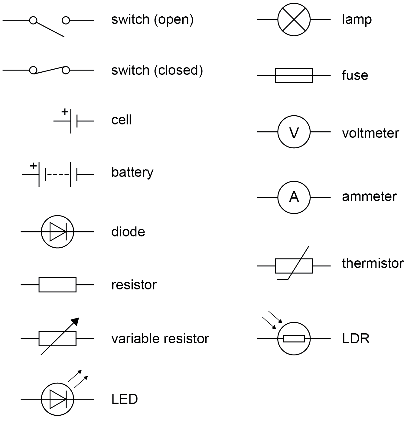
4.2.1.1 Standard circuit diagram symbols
Content | Key opportunities for skills development |
|---|
Circuit diagrams use standard symbols. Students should be able to draw and interpret circuit diagrams . | WS 1.2 |
4.2.1.2 Electrical charge and current
Content | Key opportunities for skills development |
|---|
For electrical charge to flow through a closed circuit the circuit must include a source of potential difference. | |
Electric current is a flow of electrical charge. The size of the electric current is the rate of flow of electrical charge. Charge flow, current and time are linked by the equation:
charge flow, Q , in coulombs, C current, I , in amperes, A (amp is acceptable for ampere) time, t , in seconds, s A current has the same value at any point in a single closed loop . | MS 3b, c Students should be able to recall and apply this equation. |
4.2.1.3 Current, resistance and potential difference
Content | Key opportunities for skills development |
|---|
The current ( I ) through a component depends on both the resistance ( R ) of the component and the potential difference ( V ) across the component. The greater the resistance of the component the smaller the current for a given potential difference (pd) across the component. Questions will be set using the term potential difference. Students will gain credit for the correct use of either potential difference or voltage. | |
Current, potential difference or resistance can be calculated using the equation:
potential difference, V , in volts, V current, I , in amperes, A (amp is acceptable for ampere) resistance, R , in ohms, Ω | MS 3b, c Students should be able to recall and apply this equation. |
Required practical activity 3:
Use circuit diagrams to set up and check appropriate circuits to investigate the factors affecting the resistance of electrical circuits. This should include:
- the length of a wire at constant temperature
- combinations of resistors in series and parallel.
AT skills covered by this practical activity: AT 1, 6 and 7.
This practical activity also provides opportunities to develop WS and MS. Details of all skills are given in Key opportunities for skills development .
4.2.1.4 Resistors
Content | Key opportunities for skills development |
|---|
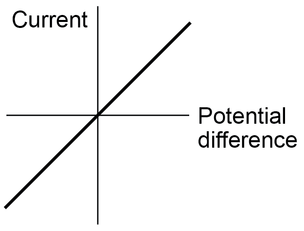
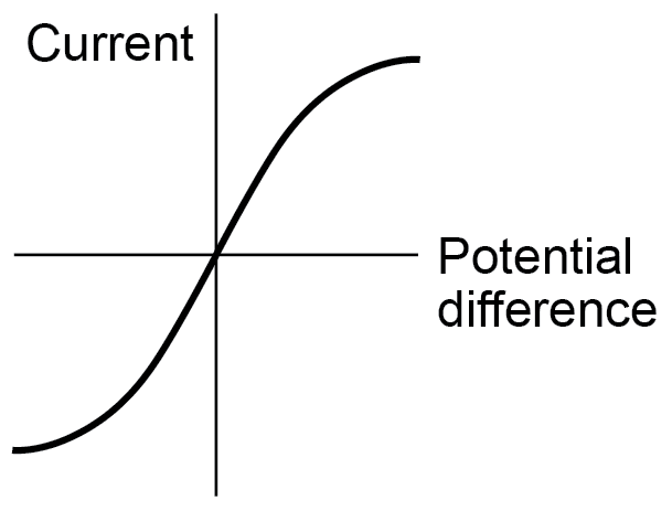
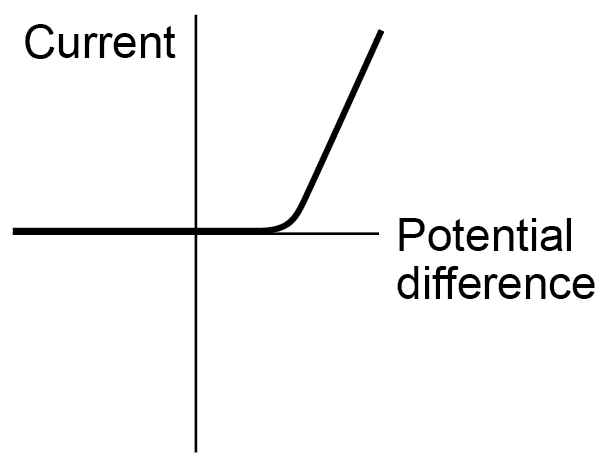
Students should be able to explain that, for some resistors, the value of R remains constant but that in others it can change as the current changes. The current through an ohmic conductor (at a constant temperature) is directly proportional to the potential difference across the resistor. This means that the resistance remains constant as the current changes. The resistance of components such as lamps, diodes, thermistors and LDRs is not constant; it changes with the current through the component. The resistance of a filament lamp increases as the temperature of the filament increases. The current through a diode flows in one direction only. The diode has a very high resistance in the reverse direction. | |
The resistance of a thermistor decreases as the temperature increases. The applications of thermistors in circuits eg a thermostat is required. The resistance of an LDR decreases as light intensity increases. | |
The application of LDRs in circuits eg switching lights on when it gets dark is required. Students should be able to: | WS 1.2, 1.4 |
- explain the design and use of a circuit to measure the resistance of a component by measuring the current through, and potential difference across, the component
- draw an appropriate circuit diagram using correct circuit symbols.
| AT 6 Investigate the relationship between the resistance of a thermistor and temperature. Investigate the relationship between the resistance of an LDR and light intensity. |
Students should be able to use graphs to explore whether circuit elements are linear or non-linear and relate the curves produced to the ir function and properties. | WS 1.2, 1.4 MS 4c, d, e |
Required practical activity 4: use circuit diagrams to construct appropriate circuits to investigate the I–V characteristics of a variety of circuit elements, including a filament lamp, a diode and a resistor at constant temperature.
AT skills covered by this practical activity: AT 6 and 7.
This practical activity also provides opportunities to develop WS and MS. Details of all skills are given in Key opportunities for skills development .
4.2.2 Series and parallel circuits
Content | Key opportunities for skills development |
|---|
There are two ways of joining electrical components, in series and in parallel. Some circuits include both series and parallel parts. For components connected in series: - there is the same current through each component
- the total potential difference of the power supply is shared between the components
- the total resistance of two components is the sum of the resistance of each component.
| |
resistance, R , in ohms, Ω For components connected in parallel: - the potential difference across each component is the same
- the total current through the whole circuit is the sum of the currents through the separate components
- the total resistance of two resistors is less than the resistance of the smallest individual resistor.
Students should be able to: | MS 1c, 3b, 3c, 3d |
- use circuit diagrams to construct and check series and parallel circuits that include a variety of common circuit components
- describe the difference between series and parallel circuits
- explain qualitatively why adding resistors in series increases the total resistance whilst adding resistors in parallel decreases the total resistance
| AT 7 |
- explain the design and use of dc series circuits for measurement and testing purposes
| WS 1.4 |
- calculate the currents, potential differences and resistances in dc series circuits
- solve problems for circuits which include resistors in series using the concept of equivalent resistance.
Students are not required to calculate the total resistance of two resistors joined in parallel. | MS 1c, 3b, c, d |
4.2.3 Domestic uses and safety
4.2.3.1 Direct and alternating potential difference
Content | Key opportunities for skills development |
|---|
Mains electricity is an ac supply. In the United Kingdom the domestic electricity supply has a frequency of 50 Hz and is about 230 V. Students should be able to explain the difference between direct and alternating potential difference. | |
4.2.3.2 Mains electricity
Content | Key opportunities for skills development |
|---|
Most electrical appliances are connected to the mains using three-core cable. The insulation covering each wire is colour coded for easy identification: live wire – brown neutral wire – blue earth wire – green and yellow stripes. The live wire carries the alternating potential difference from the supply. The neutral wire completes the circuit. The earth wire is a safety wire to stop the appliance becoming live. The potential difference between the live wire and earth (0 V) is about 230 V. The neutral wire is at, or close to, earth potential (0 V). The earth wire is at 0 V, it only carries a current if there is a fault. Students should be able to explain: - that a live wire may be dangerous even when a switch in the mains circuit is open
- the dangers of providing any connection between the live wire and earth.
| WS 1.5 |
4.2.4 Energy transfers
4.2.4.1 Power
Content | Key opportunities for skills development |
|---|
Students should be able to explain how the power transfer in any circuit device is related to the potential difference across it and the current through it, and to the energy changes over time :
power, P , in watts, W potential difference, V , in volts, V current, I , in amperes, A (amp is acceptable for ampere) resistance, R , in ohms, Ω | MS 3b, c WS 4.5 Students should be able to recall and apply both equations. |
4.2.4.2 Energy transfers in everyday appliances
Content | Key opportunities for skills development |
|---|
Everyday electrical appliances are designed to bring about energy transfers. The amount of energy an appliance transfers depends on how long the appliance is switched on for and the power of the appliance. Students should be able to describe how different domestic appliances transfer energy from batteries or ac mains to the kinetic energy of electric motors or the energy of heating devices. Work is done when charge flows in a circuit. The amount of energy transferred by electrical work can be calculated using the equation: | |
energy transferred, E , in joules, J power, P , in watts, W time, t , in seconds, s charge flow, Q , in coulombs, C potential difference, V , in volts, V | MS 3b, c Students should be able to recall and apply both equations. WS 1.4 |
Students should be able to explain how the power of a circuit device is related to: - the potential difference across it and the current through it
- the energy transferred over a given time.
Students should be able to describe, with examples, the relationship between the power ratings for domestic electrical appliances and the changes in stored energy when they are in use. | WS 1.2 |
4.2.4.3 The National Grid
Content | Key opportunities for skills development |
|---|
The National Grid is a system of cables and transformers linking power stations to consumers. | |
Electrical power is transferred from power stations to consumers using the National Grid. Step-up transformers are used to increase the potential difference from the power station to the transmission cables then step-down transformers are used to decrease, to a much lower value, the potential difference for domestic use. Students should be able to explain why the National Grid system is an efficient way to transfer energy. | The construction and operation of transformers is covered Transformers (HT only) . WS 1.4 |
4.2.5 Static electricity (physics only)
4.2.5.1 Static charge
Content | Key opportunities for skills development |
|---|
When certain insulating materials are rubbed against each other they become electrically charged. Negatively charged electrons are rubbed off one material and on to the other. The material that gains electrons becomes negatively charged. The material that loses electrons is left with an equal positive charge. When two electrically charged objects are brought close together they exert a force on each other. Two objects that carry the same type of charge repel. Two objects that carry different types of charge attract. Attraction and repulsion between two charged objects are examples of non-contact force. Students should be able to: - describe the production of static electricity, and sparking, by rubbing surfaces
- describe evidence that charged objects exert forces of attraction or repulsion on one another when not in contact
- explain how the transfer of electrons between objects can explain the phenomena of static electricity.
| |
4.2.5.2 Electric fields
Content | Key opportunities for skills development |
|---|
A charged object creates an electric field around itself. The electric field is strongest close to the charged object. The further away from the charged object, the weaker the field. A second charged object placed in the field experiences a force. The force gets stronger as the distance between the objects decreases. Students should be able to: - draw the electric field pattern for an isolated charged sphere
- explain the concept of an electric field
| |
- explain how the concept of an electric field helps to explain the non-contact force between charged objects as well as other electrostatic phenomena such as sparking.
| WS 1.2 , 1.5 |